Datei:Crystal radio with impedance matching.svg

Originaldatei (SVG-Datei, Basisgröße: 677 × 426 Pixel, Dateigröße: 32 KB)
![]()
Diese Datei und die Informationen unter dem roten Trennstrich werden aus dem zentralen Medienarchiv Wikimedia Commons eingebunden.
![]()
Beschreibung
| Beschreibung |
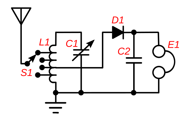
English: A crystal radio receiver circuit that uses impedance matching to increase the power transferred from the antenna through the receiver to the earphone E1. This type of circuit was used in higher quality radios around 1920. Maximum power is transferred from one circuit to another when their impedance (resistance) is equal. However, in a crystal receiver, the impedance of the antenna-ground circuit (around 10-200 ohms) is far less than the impedance of the tuned circuit (L1, C1) (thousands of ohms at resonance) and varies depending on the length of the antenna, etc.. Therefore the antenna is connected to a tap across only a portion of the coil's turns, using a multiposition switch, S1. This makes the tuning coil L1 act as an impedance matching autotransformer in addition to its tuning function, transforming the high impedance of the tuned circuit down by the square root of the turns ratio to match the antenna. The switch S1 is adjusted until the radio station is loudest in the earphone. The impedance of the crystal detector D1 is also matched to the tuned circuit by connecting the detector, like the antenna, to a tap on the coil. In addition to improving power transfer, impedance matching also improves selectivity of the receiver (its ability to reject interfering signals at nearby frequencies) by reducing the resistive "loading" of the tuned circuit, increasing the Q factor. |
| Datum | |
| Quelle | Eigenes Werk |
| Urheber | Chetvorno |
| SVG‑Erstellung |
Lizenz
I, Chetvorno, the author of this drawing, release it into the public domain for any use whatever
| Ich, der Urheberrechtsinhaber dieses Werkes, veröffentliche es als gemeinfrei. Dies gilt weltweit. In manchen Staaten könnte dies rechtlich nicht möglich sein. Sofern dies der Fall ist: Ich gewähre jedem das bedingungslose Recht, dieses Werk für jedweden Zweck zu nutzen, es sei denn, Bedingungen sind gesetzlich erforderlich. |
Dateiversionen
Klicke auf einen Zeitpunkt, um diese Version zu laden.
| Version vom | Vorschaubild | Maße | Benutzer | Kommentar | |
|---|---|---|---|---|---|
| aktuell | 06:05, 9. Mai 2017 | | 677 × 426 (32 KB) | Chetvorno | Replaced invalid Inkscape SVG version with "plain SVG" version that passes validation |
| 04:32, 28. Jan. 2016 |  | 677 × 426 (40 KB) | Chetvorno | Increased line widths and tweaked location of components | |
| 04:24, 28. Jan. 2016 |  | 677 × 426 (40 KB) | Chetvorno | Increased line width and tweaked location of components | |
| 11:40, 20. Mai 2010 |  | 677 × 426 (38 KB) | Chetvorno | {{Information |Description={{en|A crystal radio receiver circuit that uses Wikipedia:impedance matching to increase the power transferred from the antenna to the earphone. The maximum power is transferred from one circuit to another when their imped |
Dateiverwendung
Die folgenden 2 Seiten verwenden diese Datei:
Globale Dateiverwendung
Die nachfolgenden anderen Wikis verwenden diese Datei:
- Verwendung auf en.wikipedia.org
- Verwendung auf es.wikipedia.org